Reading time is around minutes.
The Layout -
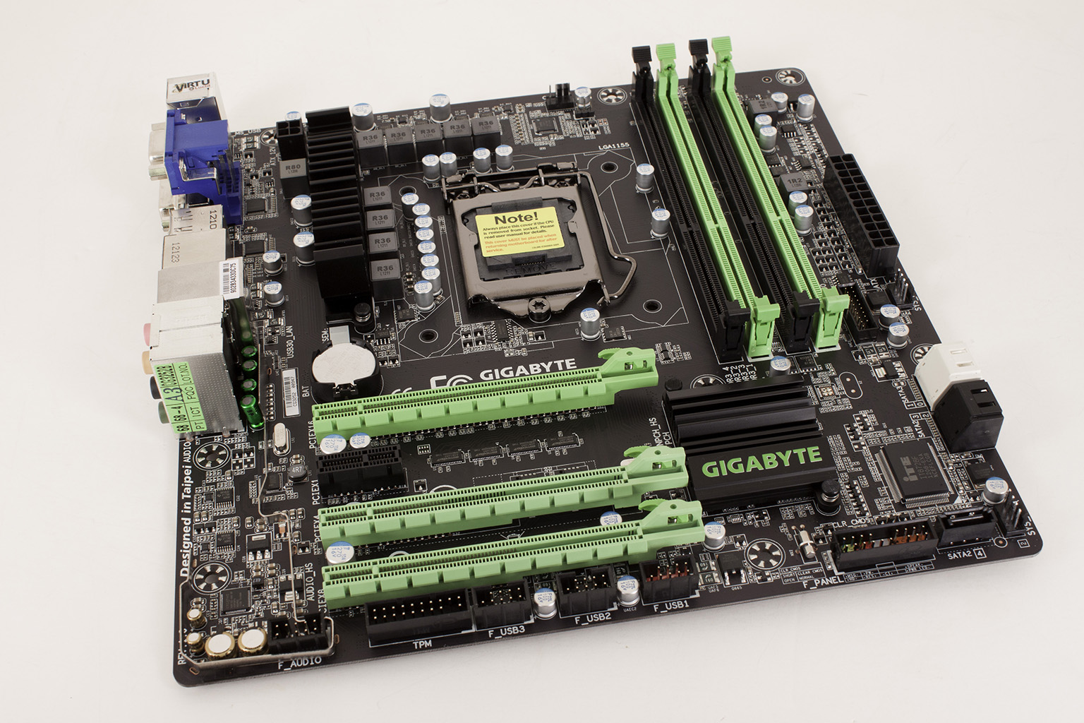
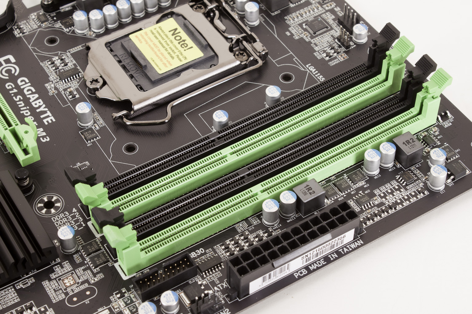
The layout of any motherboard is important. Even simple mistakes in component placement or the signal traces can cause major issued in performance and stability. With the ATX form factor we find that this is even truer; the devices we drop onto them demand more and cleaner power while the signal speeds push faster and faster. The G1.Sniper M3 is a Micro ATX motherboard. This means that it is going to be shorter than the standard ATX board, but will still have the same width. The size makes it suitable for a small form factor gaming rig, but Gigabyte has made sure not to skimp on the power or features. Starting off in our normal spot we find the typical four RAM slots for the dual channel memory supported by both Sandy Bridge and Ivy Bridge. You can also see the 24-pin ATX power connector, the front panel USB 3.0 header, and two of the four 4-pin PWM fan headers.
 |
 |
A closer look at the CPU socket shows us the level of trace tuning that Gigabyte went to for this board. You can see this very clearly around the heat sink mounting holes. Getting the trace layout correct is a very important part of designing a motherboard as mistakes at this level can be exceptionally difficult to fix later.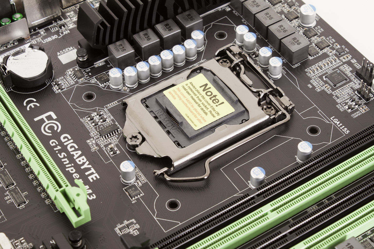 Looking at the power regulation we were a little surprised that the cooling was not a little better on it. VRMs can get pretty warm especially of the board is used for overclocking (and with water cooling). We will be keeping an eye on this to make sure that it does not get too warm during usage. We also find the 4-Pin Aux power connector here. It is in a rather awkward place so as always we recommend that you use an adapter.
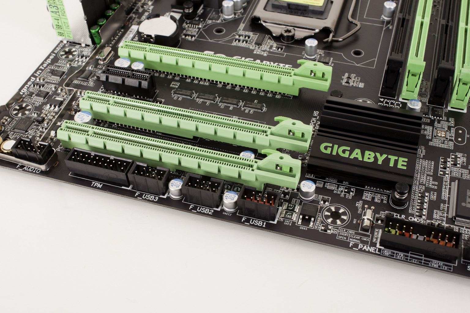
Moving down the board we come to one of the major features of the G1.Sniper M3; the SoundCore 3D. Here you can see that it has what looks like an EMI shield around the components. Unfortunately it is not going to be of any use in that capacity and is really only for appearances. The band does wrap around all of the components, but it does not provide any real separation; so while it looks nice, it will not have much real benefit in terms of audio quality or performance.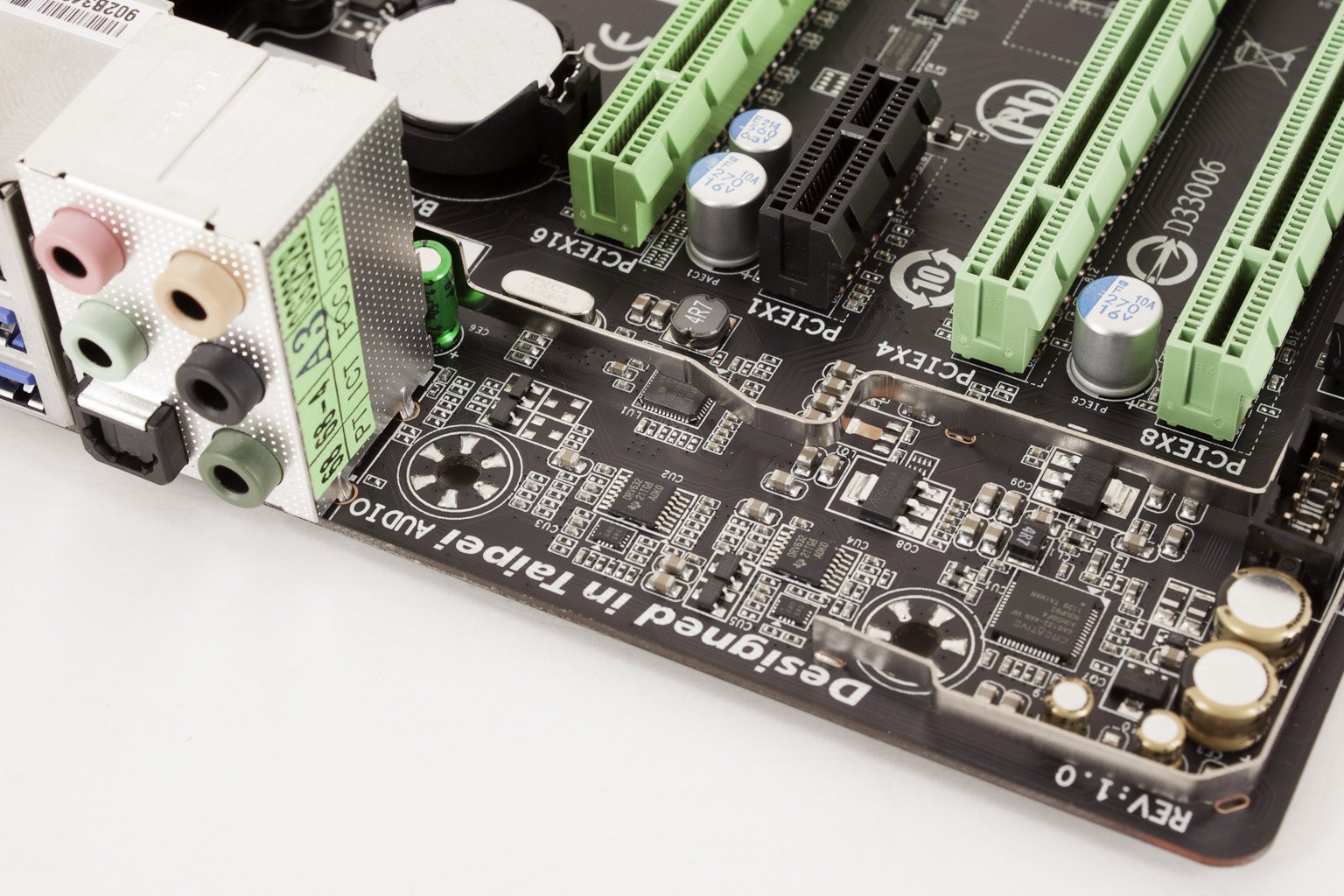 Taking a look at the PCIe slots on the G1.Sniper M3 we fins three that are x16 mechanical, but only one of them is full x16 electrical. This is, of course, the top slot. Slot 2 is x4 and slot 3 (of the x16 slots) is x8. When you have a card in slot 3 both slots one and three will run at x8. Those are also the only two slots that are Gen 3. The x4 slot and the x1 slot are Gen 2 only.
 |
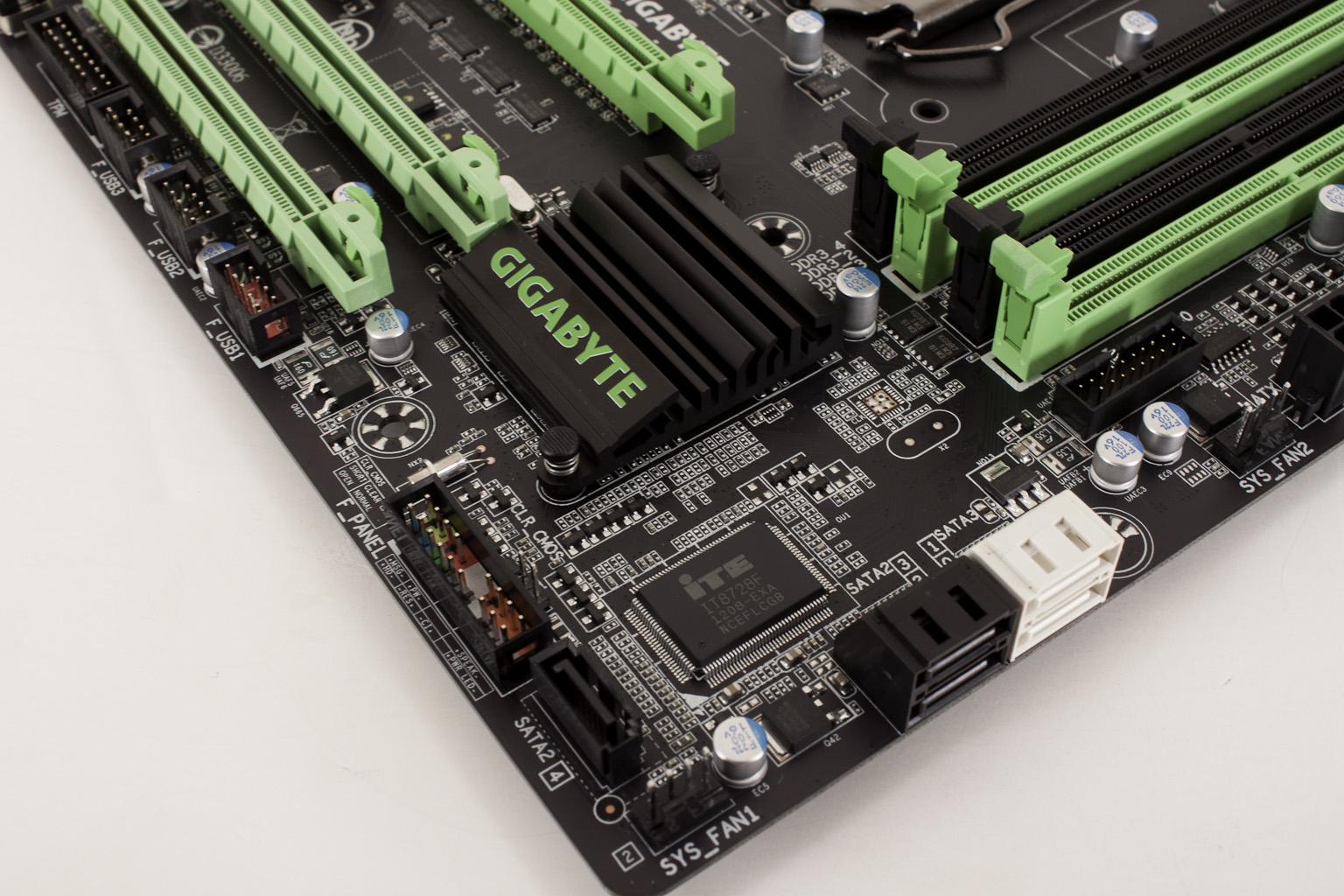 |
The rest of the board is well laid out with multiple headers for USB 2.0 available. You also get a 20+1 TMP header and what looks like an eSATA front panel port right next to the front panel headers. This is split with the eSATA port on the I/O panel. For the rest of your drive needs Gigabyte gives you two SATA 2.0 (the black ports) and 2 SATA 3.0 (the white ports).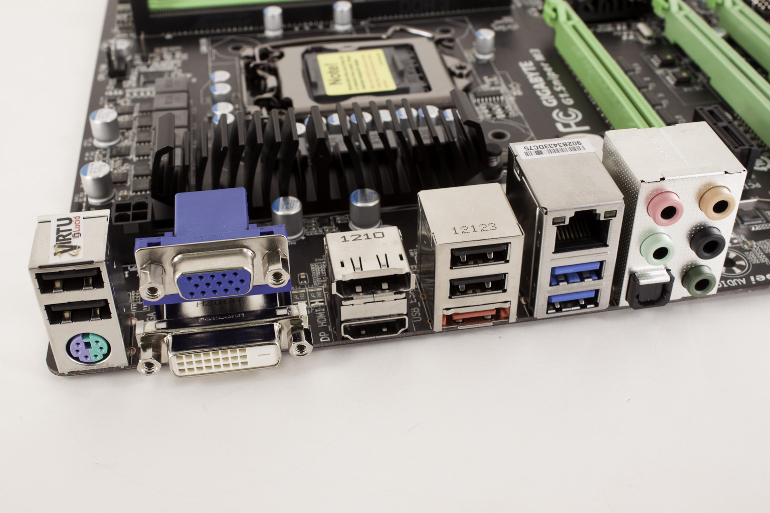
Looking at the I/O panel things are fairly typical with four USB 2.0 ports, a combination PS/2 port, 2 USB 3.0 ports, a gigabit Ethernet port and typical set of audio out options. For video you get VGA, DVI, HDMI and Display port for video (if you chose to use the IGPU on your CPU).
In all the G1.Sniper M3 is a well-designed product. Gigabyte has put some thought into the layout and in keeping with their other higher end boards they are going with a better class of components. The capacitors are a higher standard solid cap as well as Nichicon caps for their audio components (but not on the rest of the board). Unless there are issues with the BIOS or other items that an inspection of the design and layout will not note we would expect the G1.Sniper M3 to perform well.
