Reading time is around minutes.
The Layout -
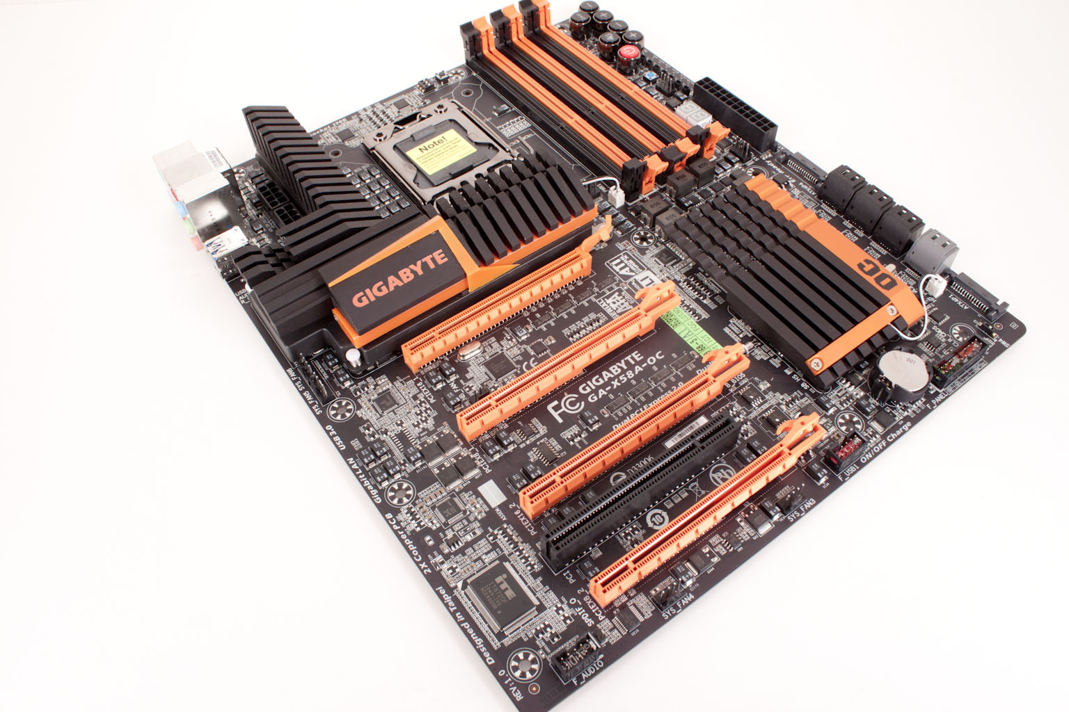
The layout of any motherboard is important. Even simple mistakes in component placement or the signal traces can cause major issued in performance and stability. With the ATX form factor we find that this is even truer; the devices we drop onto them demand more and cleaner power while the signal speeds push faster and faster. If you have read any of my reviews you know that I am big on the board design and layout. With each new product I like to take a look at the general build and then try and identify the design choices and why they were made. With a product like the X58A-OC there even more questions on design and layout. As you can probably guess the X58A-OC is based on the standard ATX layout. I was a little surprised to see this as I would have thought that HiCookie might have wanted to give some extra room for GPUs, tracing and other items. My thought is that the smaller (relatively) layout allows for shorter traces. Shorter traces usually equal better performance and less tuning required to make sure everything works.
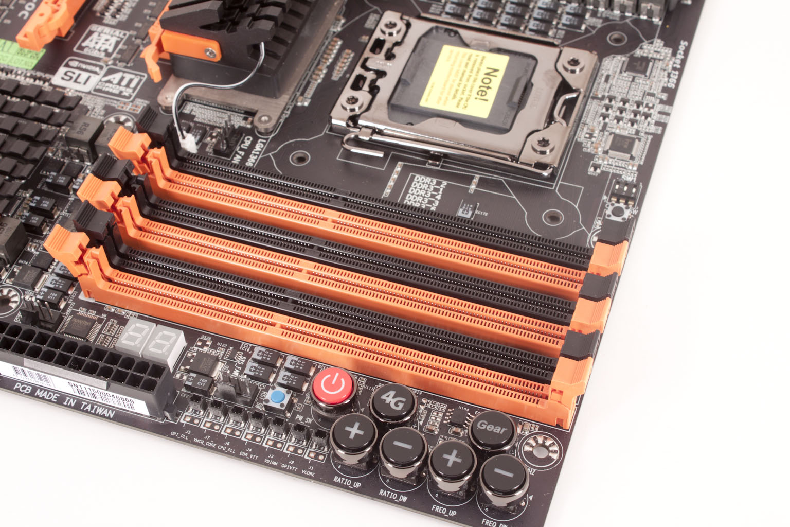
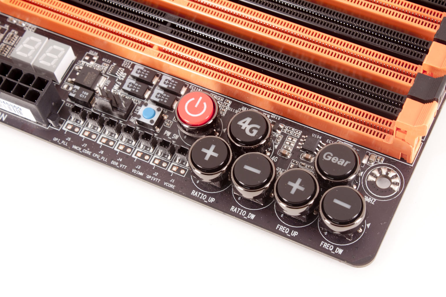
Tracing and PCB size decisions aside let’s take a look around at the X58A-OC and see what we can find. Looking at the upper right hand corner at of the X58A-OC we find the controls and the memory slots. Looking here there is something that should stand out right away. Do you see it? There are no round capacitors. These have been replaced with POSCaps. No, POS does not stand for that! POSCaps are solid electrolytic capacitors that are intended for high frequency, high heat applications. These are perfect for a motherboard that is meant to be pushed like the X58A-OC is. Other than the lack of the typical capacitor we find a bank of controls. You have the usual Power and Reset (the reset is the small blue button) along with buttons for increasing or reducing the BCLK and Ratio. Behind this row is a one-step 4GHz overclock button (the one labeled 4G). The last button is labeled Gear and switches your BCLK adjustment between 1MHz and .5MHz.
 |
 |
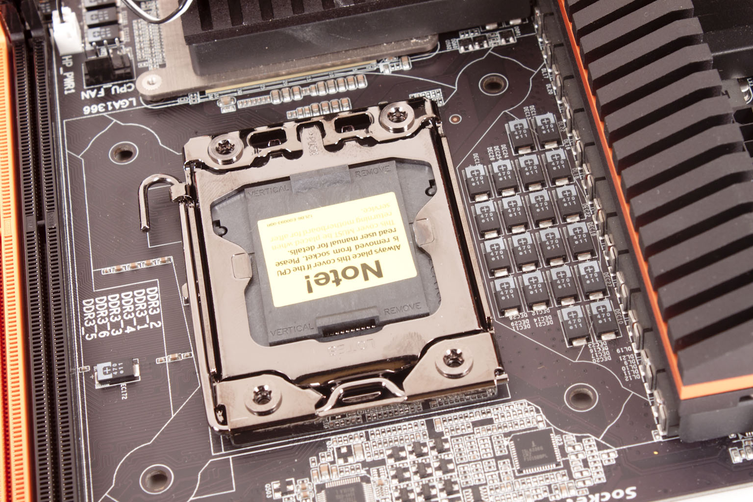
Oh yeah,… remember those voltage read cables? Well they connect right here. To round out our coverage of this small area we will point out the Dual LED diagnostic display, 24-pin power port and of course the six memory slots. Moving along we take a look at the CPU area. Notice how clean this area is? Well the reason for this is to help with airflow and cooling but it also makes things easy to insulate when you are preparing the board for sub-zero overclocking. Let’s face it when you are stuffing putty into the area around a CPU would you rather have POSCaps or some Japanese Solid Caps like you might find on other boards?
 |
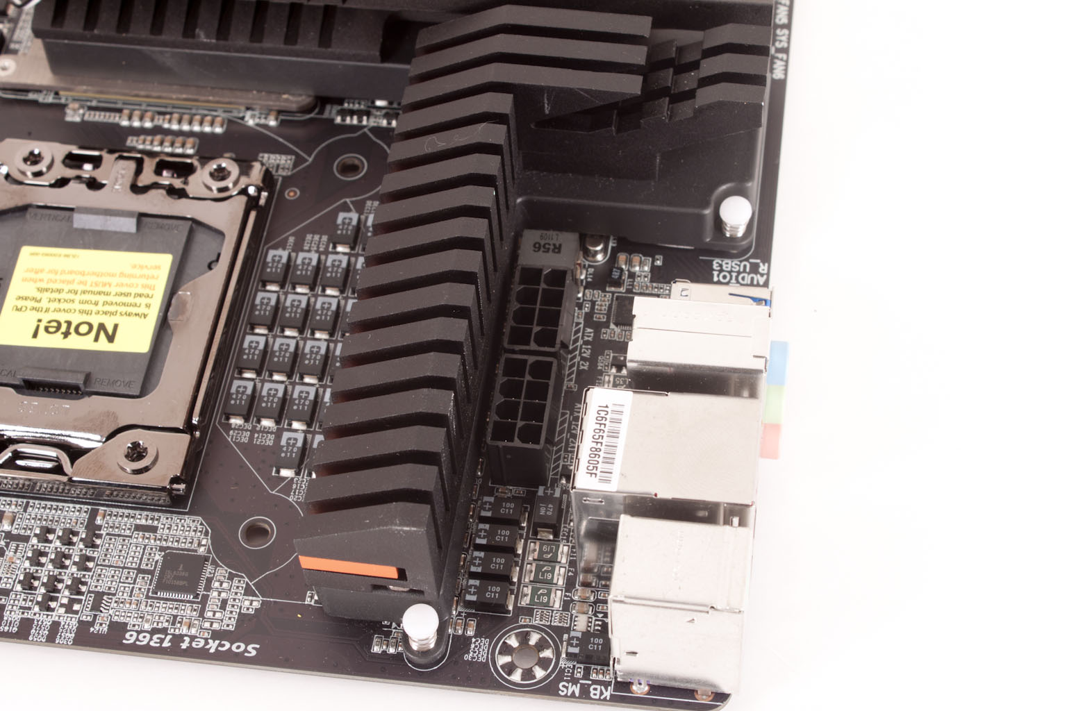 |
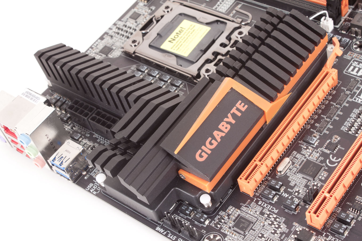
Moving on we get a good look at part of the voltage regulation cooling and also the dual 8-pin Aux power connectors. Under the large heatsink there are Driver MOSFETs and also low temp single chokes that are capable of handling up to 50A. The whole setup here combines to allow for a total estimated power output to the CPU of 1200Watts. To give you an idea of efficiency the max input is 1500 Watts so you are getting 80% efficiency from this design. This is the reason for the beefy cooling which warps around to cover the X58 chipset as well. Gigabyte added some lights to this just to keep things interesting. The cooling also helps segment the board, you might not think about this but with the sloped design of the cooling (sloped away from the primary GPU slot) you get a deflection of heat from the GPU away from the CPU area. It really is a nice design.
 |
 |
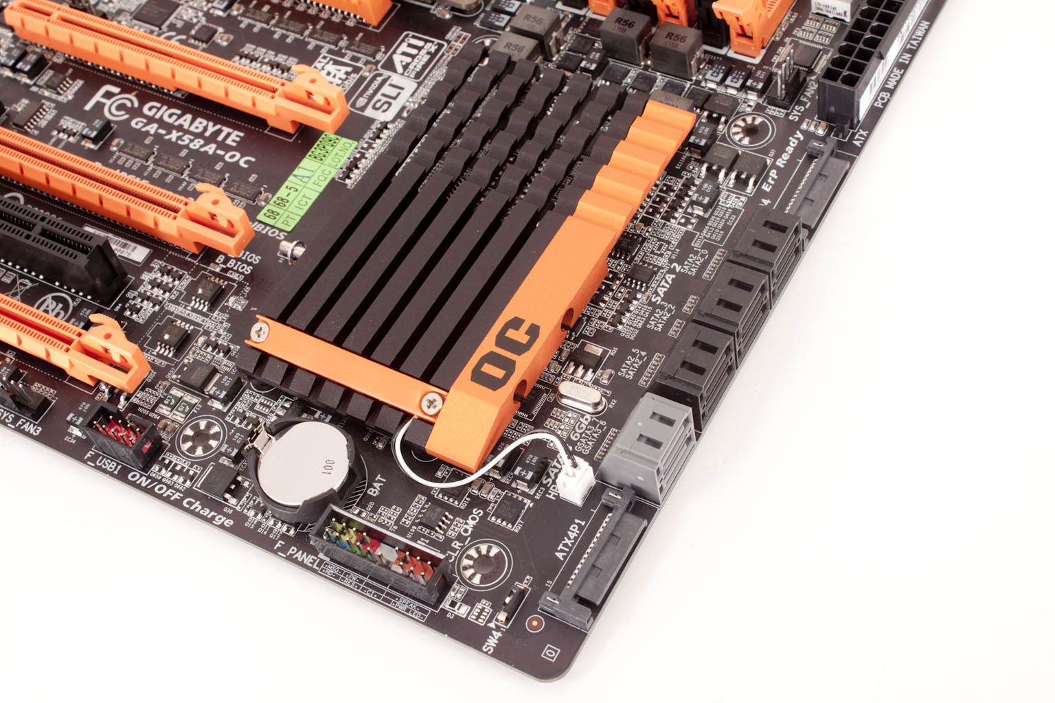
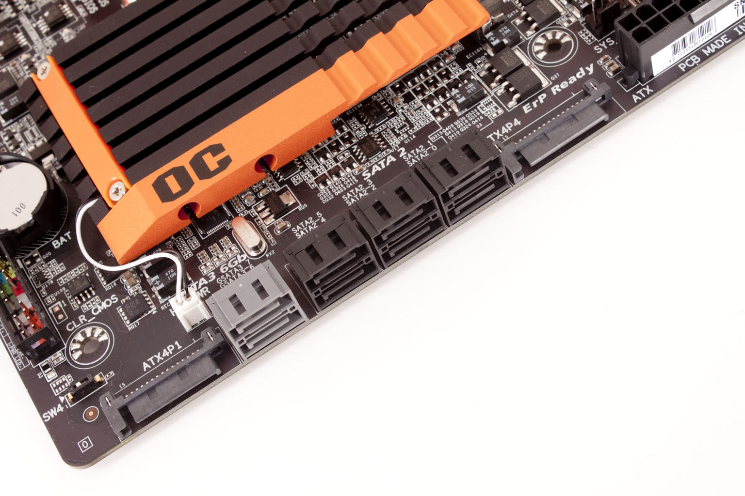
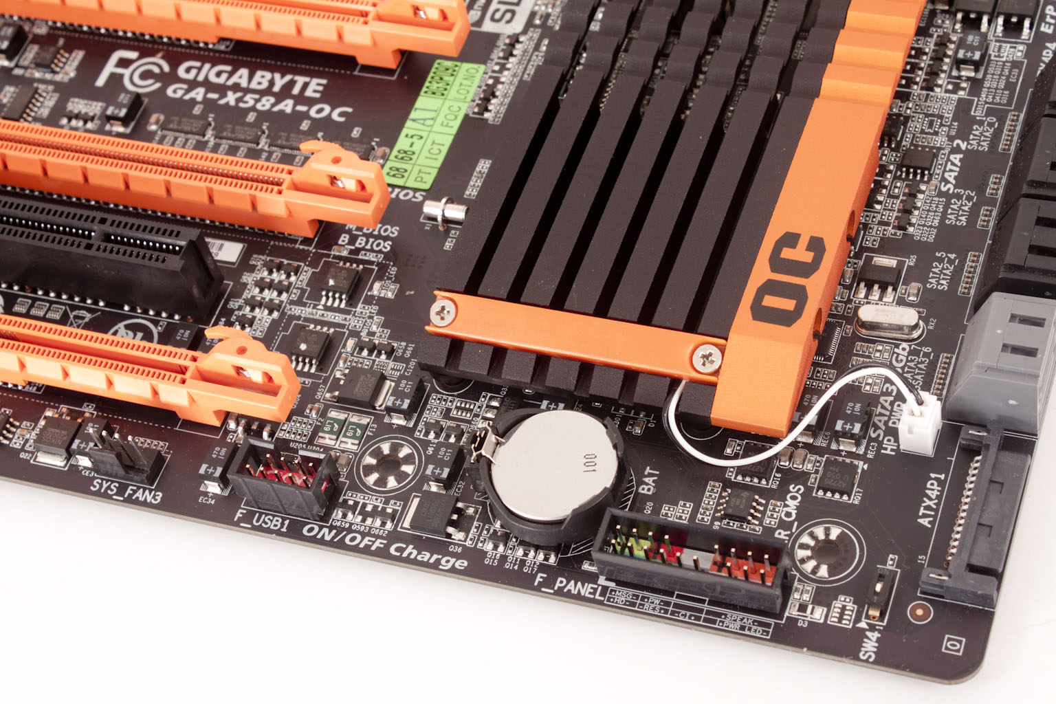
Moving on (reminds me of a movie studio tour…) well really moving down towards the bottom of the board you get a gander at the peripheral slots. You get four x16 mechanical slots but only two are fully x16 electrical (and stay that way when populated) these are slots one and three. The other two are x8 but are still good enough for three-way SLI or for quad crossfire. Speaking of multiple GPUs (and power along the way) HiCookie made sure there would be plenty of power for your setup not matter the number of GPUs you throw at it. There are two SATA style power connectors along the front edge of the motherboard. These are on either side of the SATA ports and with their low profile also help keep airflow going. Just behind this we find a nice looking heatsink for the IHC10R chipset. This one also has a light in it; you know just for style.
 |
|
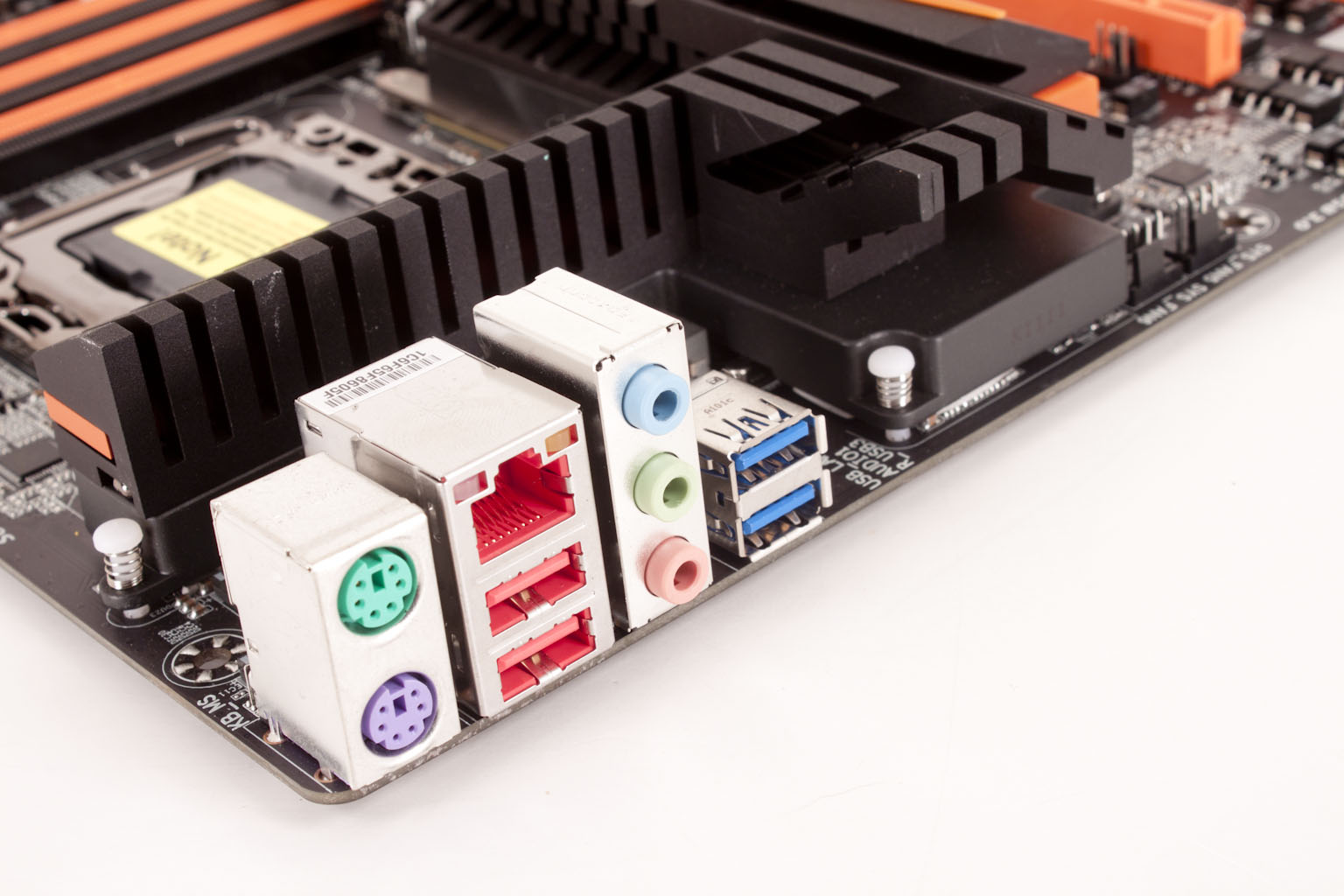
Flipping the board around we take a look at the very light I/O ports. You get the basics really. Well the USB 3.0 ports are not needed but are nice to have. The X58A-OC has some interesting design choices; HiCookie has (for the most part) made the best choice for performance and stability. At least that is what we are seeing on the surface; of course we will have to see what we get when we power it up.