Reading time is around minutes.
The Layout -
The layout of any motherboard is important. Even simple mistakes in component placement or the signal traces can cause major issued in performance and stability. With the ATX form factor we find that this is even truer; the devices we drop onto them demand more and cleaner power while the signal speeds pus faster and faster. 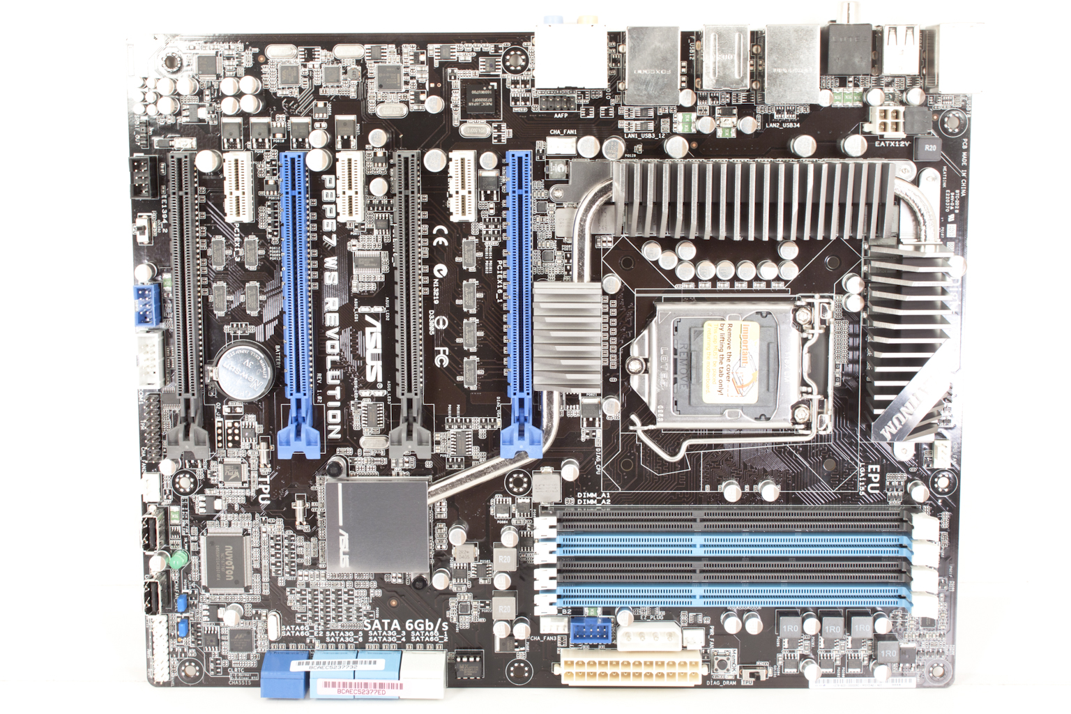
The Asus P8P67 WS is a nice looking board. The layout of the components and the cooling system give it a sense of style. It also has a very clean look to it. Some of this is from the use of solid caps and also the use of BGA (Ball Grid Array) ICs for many of the board level components instead of the more traditional kind with leads that run off of the sides of the IC. By using BGA packaging you can get better tracing layouts because the pads that the balls connect to are all under the IC instead of having to route them to the four sides of the chip.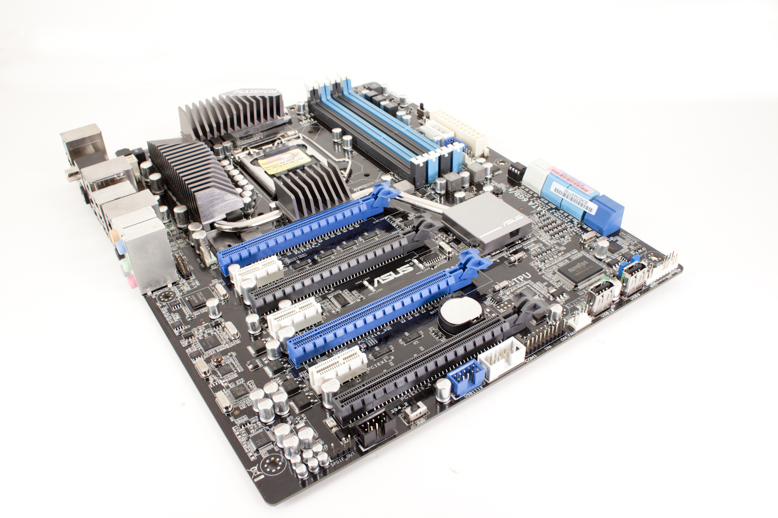
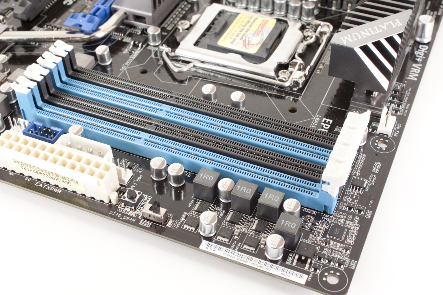
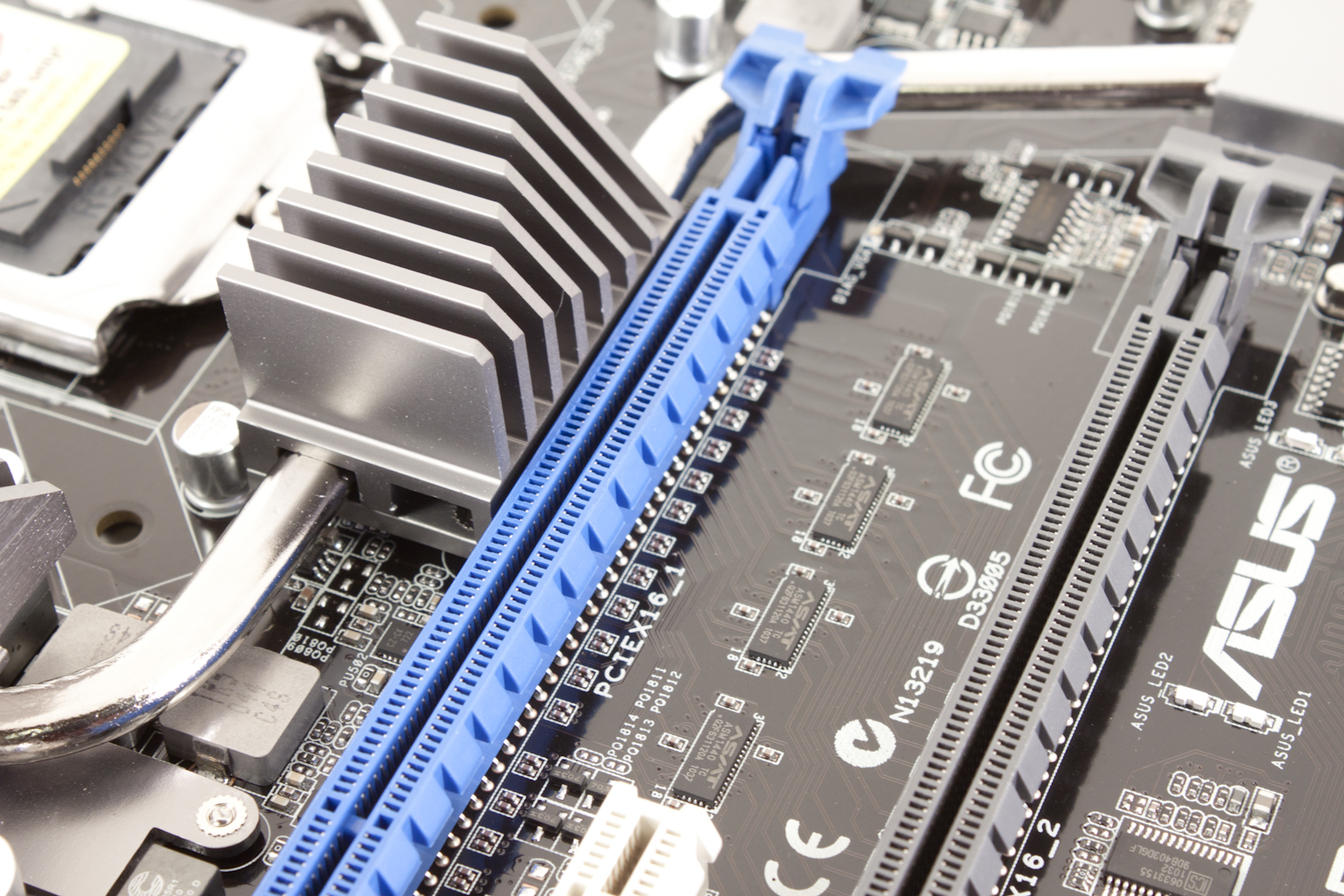
Getting in a little closer we take a look at Asus’ “one armed” RAM slots. These slots have, for the most part, been a success with the consumers. It makes installing and removing RAM very easy and in satiations where your primary GPU may be close, it eliminates the need to remove that GPU to change out RAM. The Asus MemOK! Button can be seen in this shot; if you do not know that MemOK! Does, well it can help adjust the timings on your RAM to make sure you can boot properly. Right above the MemOK! Button is a small switch labeled TPU. This is the Thermal Processing Unit switch; it lets you enable or disable this device. We will talk more about the TPU later. One slightly awkward item visible here is the 4-pin Molex connector. It sits very close to the 24-pin ATX power connector. It is also very close to a three-pin fan header and a USB header on the board.
 |
 |
 |
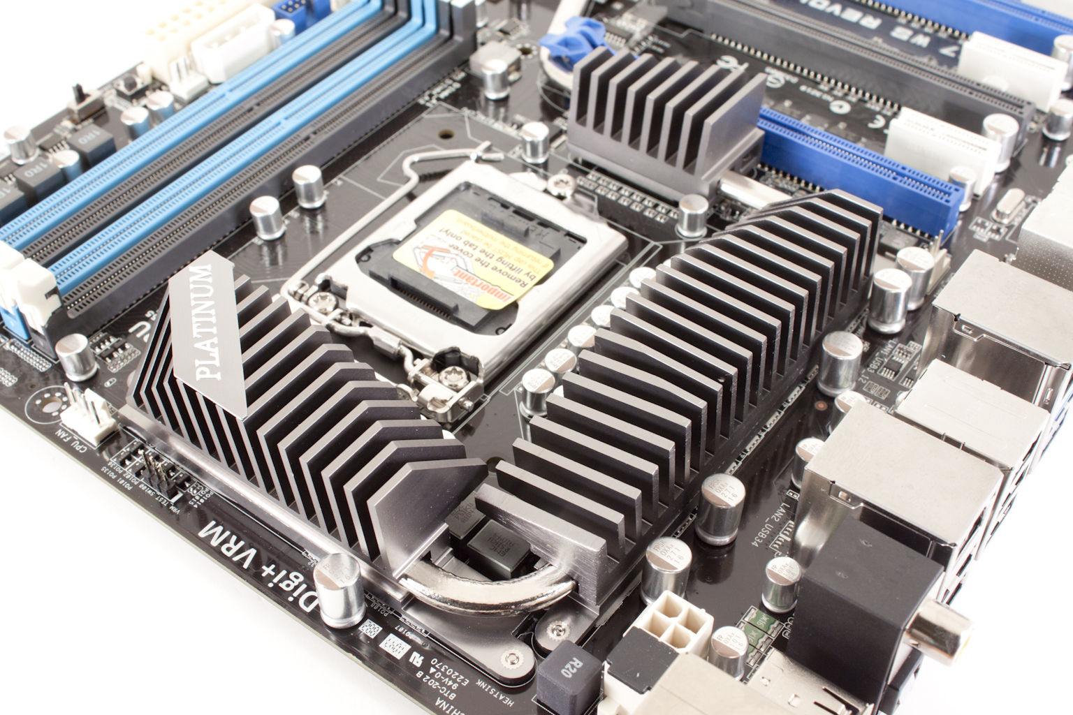
Moving on we find what looks to be a cluttered CPU area; at least that it what it seems at first glance. In reality the layout is cleaner than it appears. The sloped design of the heat sinks allows for god air movement not only through the fins but also around the CPU area itself. Those same sloped edges also help with the installation of the CPU heatsink, the 8-Pin aux power cable and also the CPU fan. It really looks like Asus listened to my complaints about the 8-pin connector as this design makes it fairly easy to install and remove that cable. You can see even more evidence of this design choice in the sloped edge visible in the second shot. It gives plenty of clearance for you to press the PCIe release lever.
 |
 |
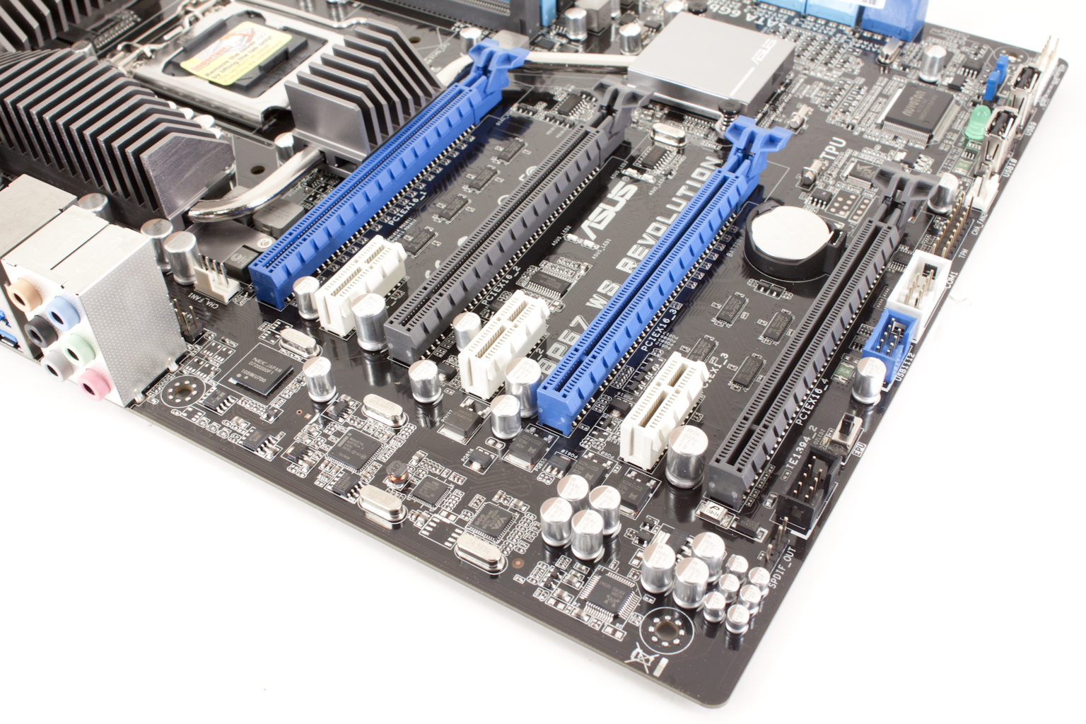
The four PCIe slots are arranged in two groups. The two Blue slots are Primary and the two Black are secondary. What this means is that if you have GPUs in the Two Blue Slots you can get dual x16 SLI thanks to the NF200 on board. However, if you put anything into the black slots the corresponding blue slot will shift down to x8. The three PCIe x1 slots do not affect the state of the other PCIe slots. Also visible in this shot are the two Intel LAN controllers, a VIA 1394a controller and an NEC USB 3.0 controller.
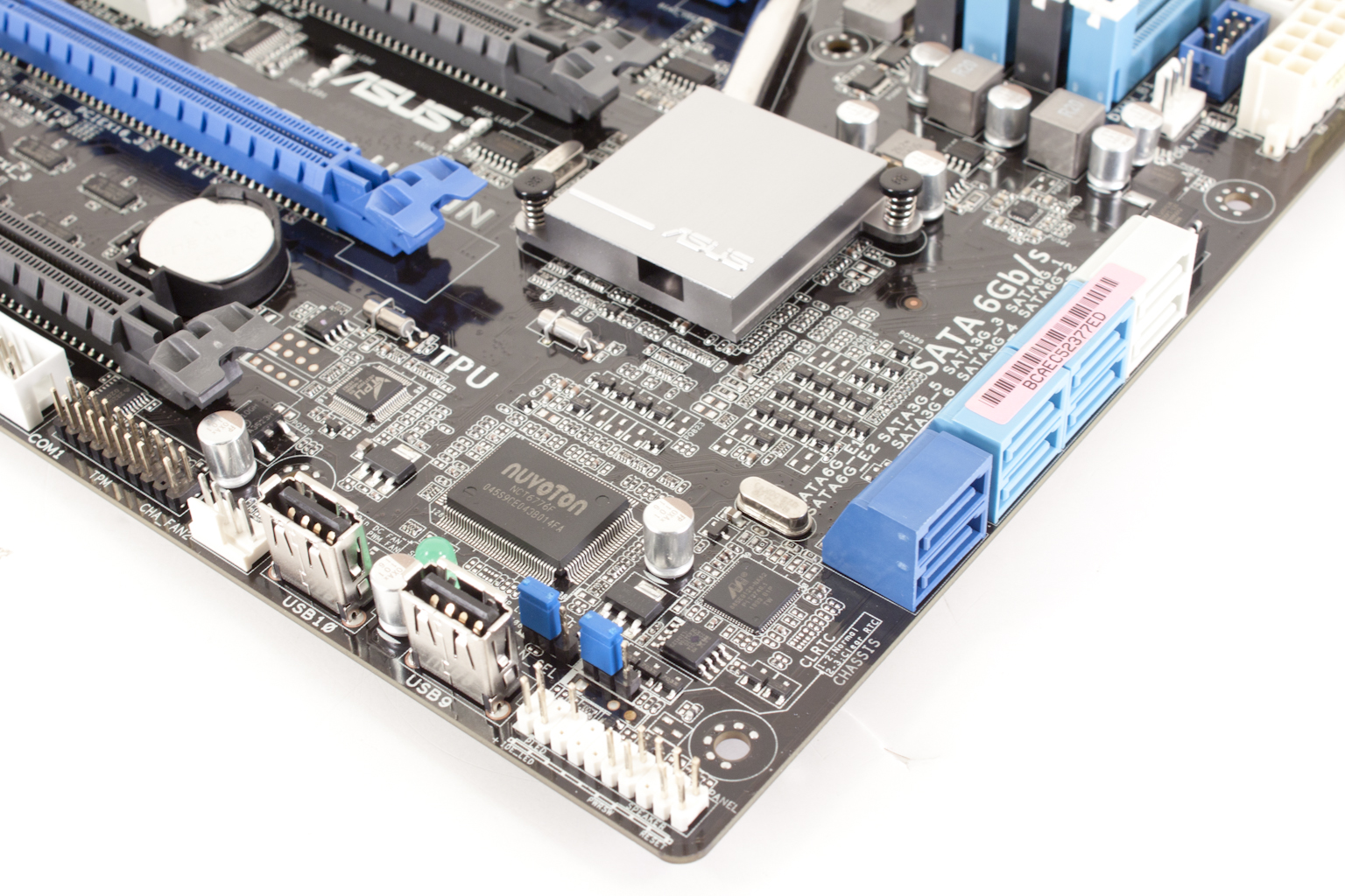
Flipping around to the front of the board we find that TPU we talked about earlier. It is barely visible in the picture below but does provide some nice functionality. We also get to see the Marvell controller that Asus is using for SATA 3.0 (in addition to the Intel one from the cougar point SB). The WS Revolution has four SATA II ports (the Blue ones) and four SATA 3.0 ports. This makes the issue that has flown around the internet easy to get around. Don’t get me wrong here; the failing SATA ports is a big issue and Intel is doing the right thing by replacing the affected chips. However, if you have one of these now (or are thinking of getting one) you can simply by-pass those ports and use the SATA 3.0 ones instead. It is also a good excuse to move to SATA 3.0 (at least that is what you can tell your wife/girlfriend/mom).
Now, I am sure some of you are wondering about the two visible USB ports. Well, I can explain those; in the world of graphical design, 3D Animation, and CAD you very often have to use a security dongle to enable all of the functions of your application. We have one that is used for Lightwave along with a few other Apps that we use in the lab. Having these internal ports puts these keys out of sight and with a lockable case they are fairly secure as well. It is a nice feature for the workstation world and one that I am glad to see. Right next to the USB ports (well after a four-pin fan header) are a group of pins labeled TPM (Trusted Platform Module). This is where you attach that diagnostic module we showed you earlier.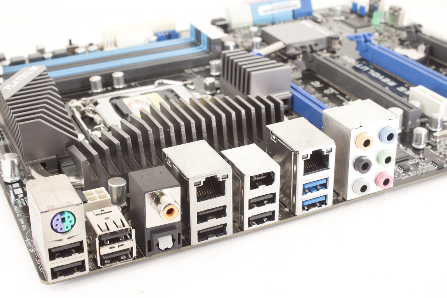
The I/O ports on the P8P67 WS are fairly typical. You get the typical combination PS/2 port with the Dual USB underneath. Asus has thrown in a total of eight USB 3.0 ports on the back I/O plane along with two USB 3.0 port and a 1394a port. This gives you quite a bit of USB functionality. In the professional world this means a ton of external drives. I know that typically run 3-4 USB drives including a 500GB USB 3.0 drive from Seagate (Black Armor PS110 USB 3.0). The two LAN ports are Intel GBe ports while the audio is provided by Realtek. All-in-all the P8P67 WS Revolution is not a bad design for a motherboard. You also get a nice selection of components for the workstation crowd.
