Reading time is around minutes.
The Layout -
The layout of any motherboard is important. Even simple mistakes in component placement or the signal traces can cause major issued in performance and stability. With the ATX form factor we find that this is even truer; the devices we drop onto them demand more and cleaner power while the signal speeds push faster and faster. MSI has been working hard on their layout and the design choices they make in regards to their motherboards. Not all that long ago the moved away from the traditional Solid Caps around the CPU socket and went with self-healing parts. These are called Hi-c CAPs and have a rather interesting feature to them. As the material inside them heats up it becomes malleable. This means that they can reform as they cool so it is sort of like getting new caps every time you power up.

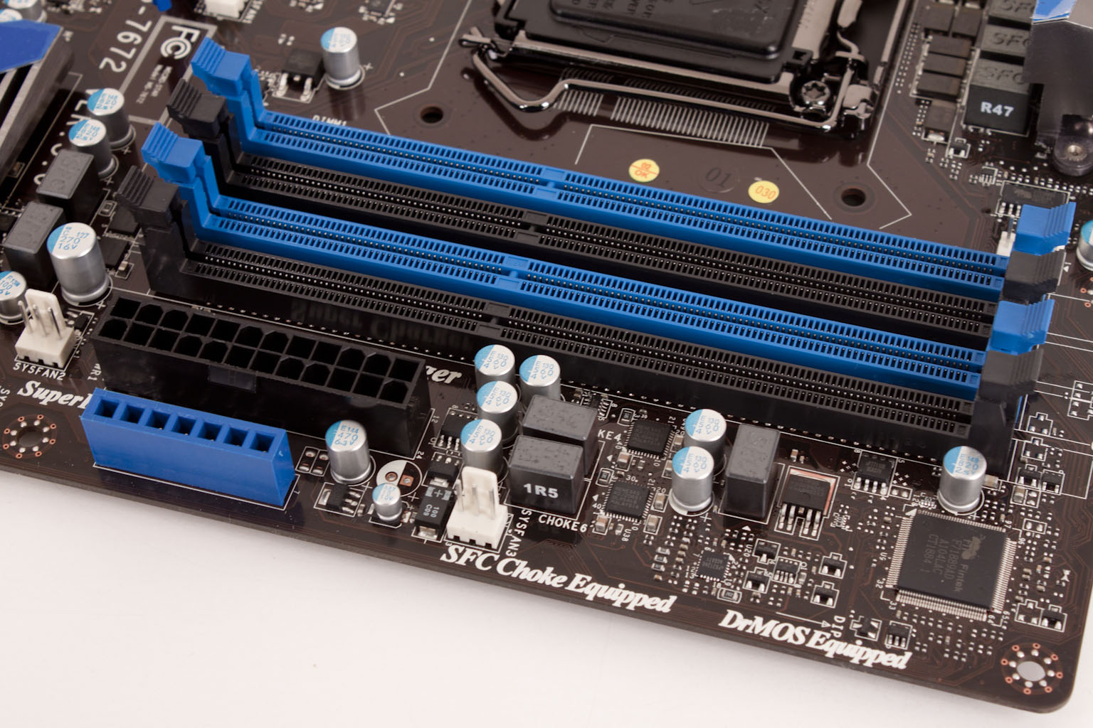
When we take a look at the actual board we really are not seeing anything that much out of the ordinary. You have the same basic ATX layout that you find on other motherboards. You could almost match them up part for part and find the same the same pieces (well maybe difference pieces but in the same place). However there are still differences in design logic that can make one board perform better or be easier to use than another. Taking a look at the upper right-hand side of the board we find what looks like the typical RAM slots, Power connector etc. However there is a difference here. On many boards have voltage read points all you get is a series of pads or a line of connectors for extension cables. On the Z68A-GD80 you get a block that allows you to use the typical leads from a multimeter.
 |
 |
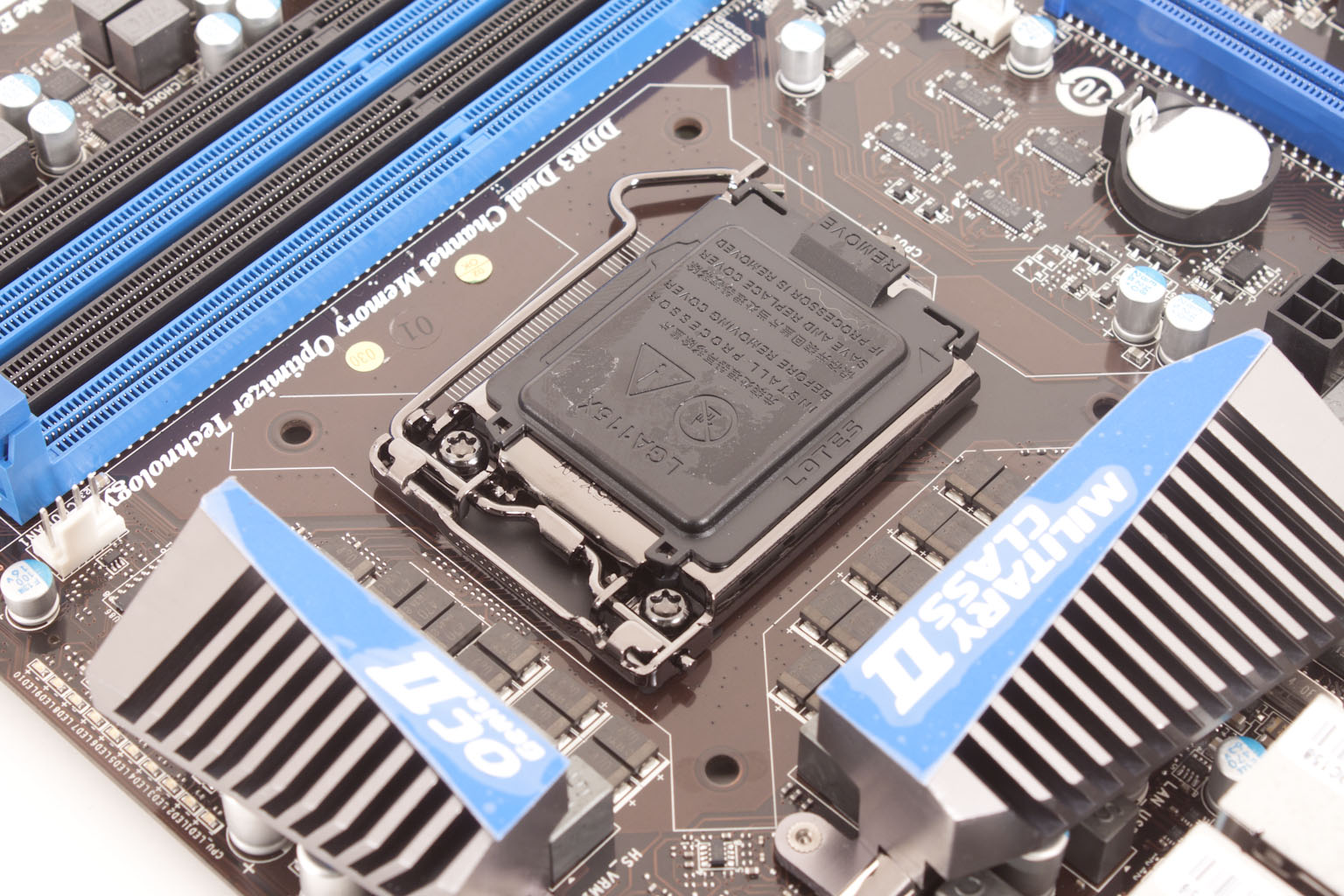
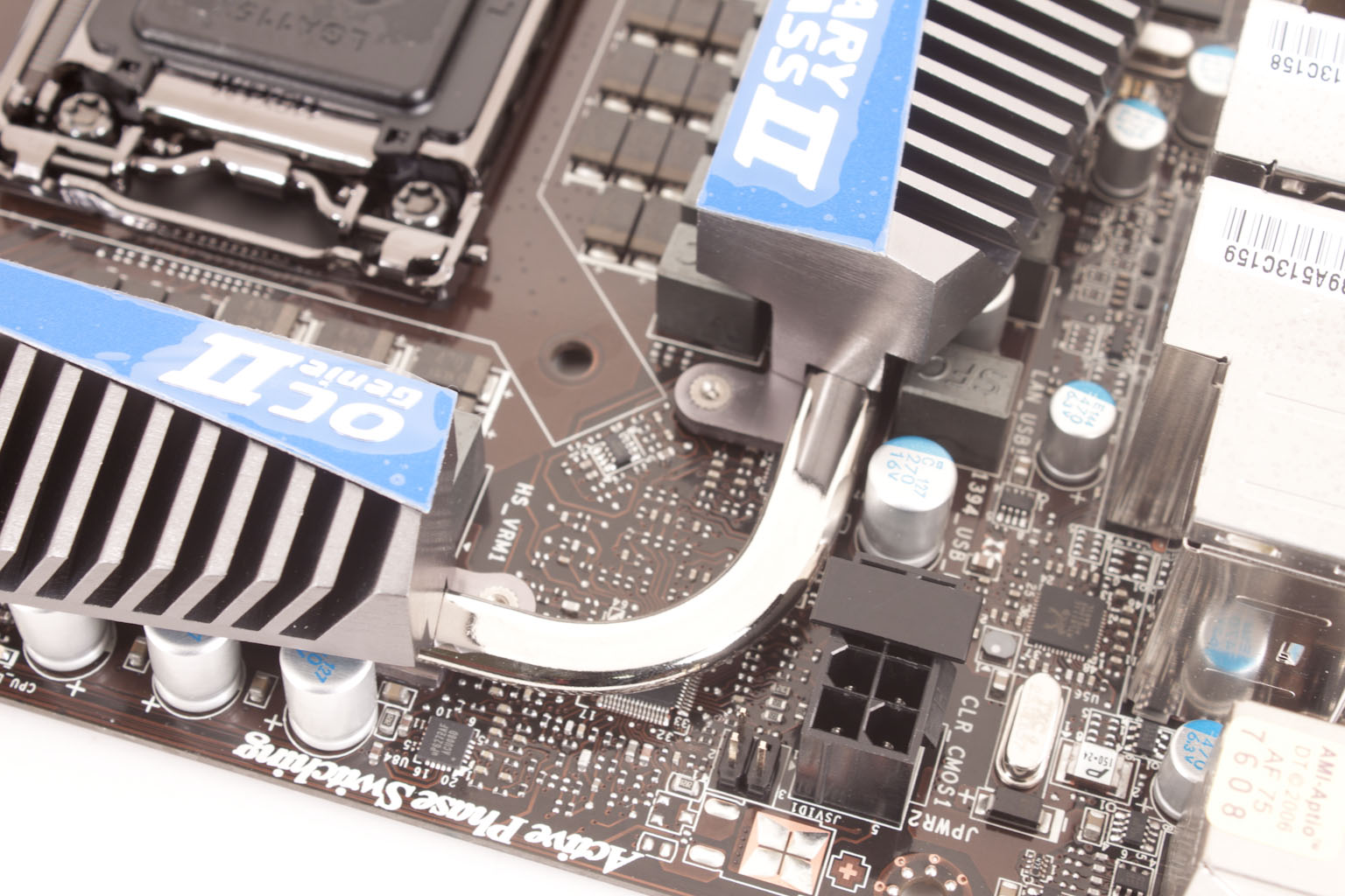
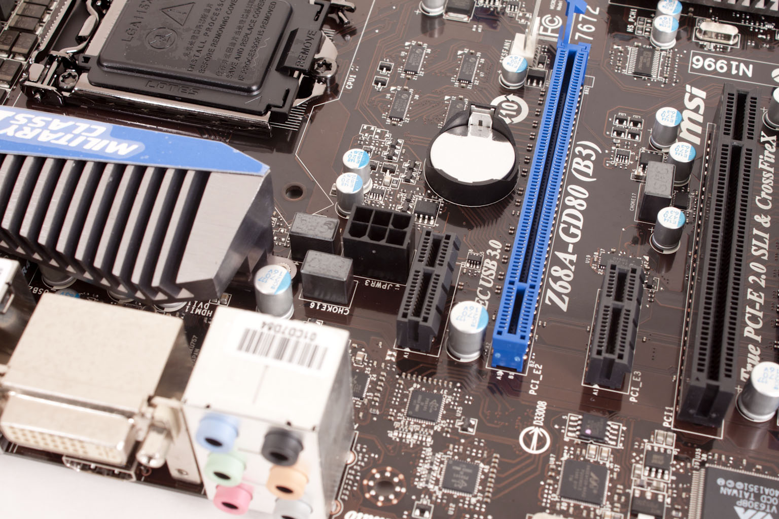
Looking at the CPU socket area we get a good look at some of the new choices that MSI has made. You can see the Hi-c CAPs around the CPU. This is an area that truly needs components like this as this area pulls the most voltage and generates the most heat. This level of heat, especially when overclocking can affect the life of even the best Solid Cap. Another item that MSI has chosen is SFCs This stands for Super Ferrite Choke and is supposed to yield 30% better performance for that component when compared to your standard choke. For those that are keeping score the CPU Socket is a Lotes socket, although I have to say that I have never had an issue with the Foxconn socket. Looking at the cooling here we find that it is centered on only the voltage regulators. This type of cooling does concern me as it leaves the caps and chokes out of direct contact but does allow them to affect the air temperature around the heat sink and lessen its efficiency.
 |
 |
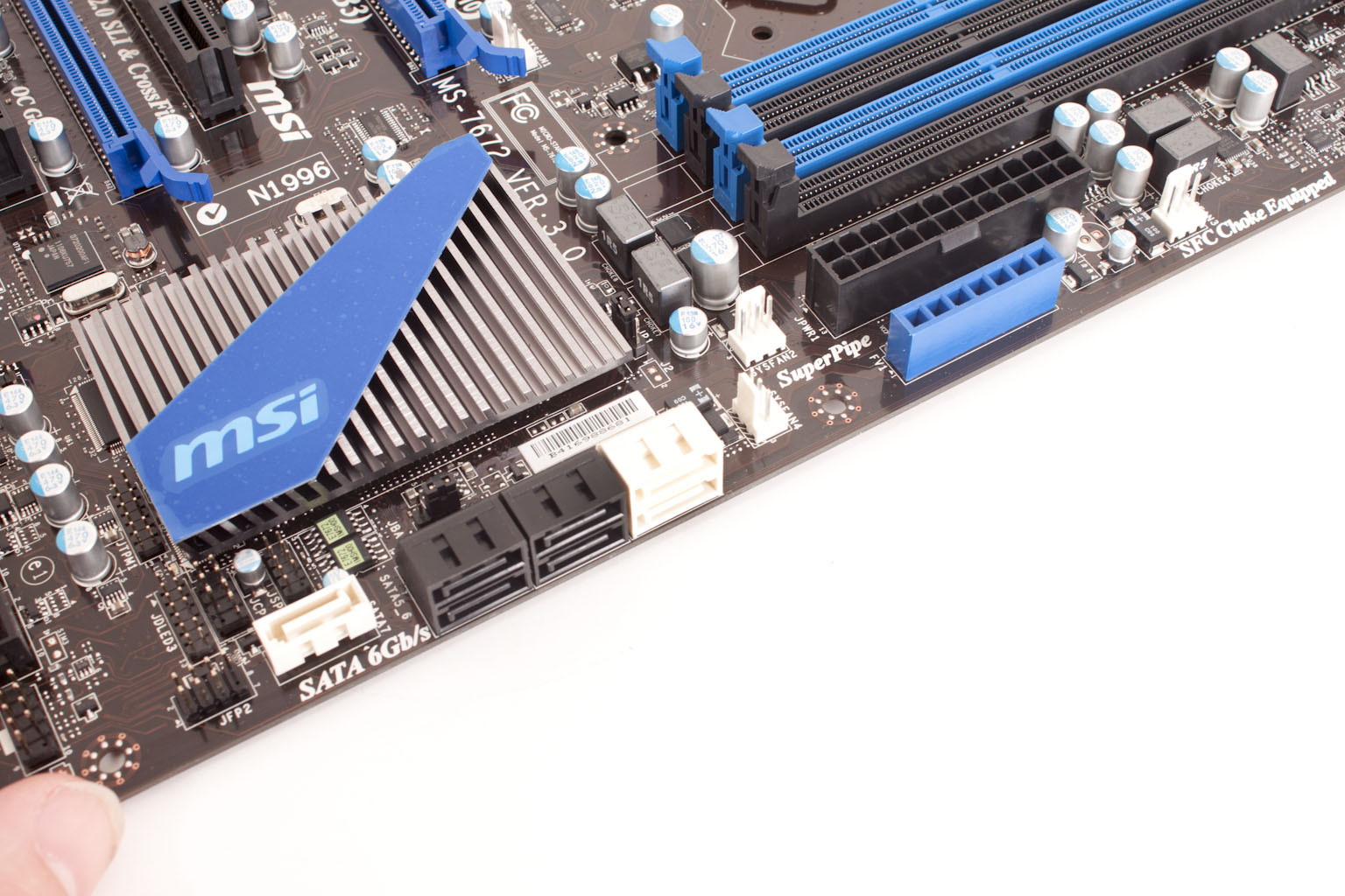
We were talking about power and the way that MSI is dealing with in on the Z68A-GD80 (that is what all that talk about CAPs and Regulators was about). So let’s talk about the power connectors and their placement on the board. MSI has the typical 24-pin ATX connector as well as an 8-Pin connector in the typical place. But, where most companies drop a Molex connector MSI has used a 6-pin PCIe power connector on the board. This actually can almost replace the two power adapters that some companies use.
 |
 |
Now we move down into the peripheral area of the GD80 and find what looks like a very light number of slots. You get three PCIe x16 mechanical slots, only one (the first or top slot) is fully x16 and that is when the second one is empty. If you have cards in both then they both function as x8 which is good enough for a couple of nVidia or ATi GPUs. The bottom PCIe slot is x4 only. As an interesting note, if you put a PCIe device into the last slot that is at least x4 you lose some components on the board. You will lose the ability to run all of the following; 1 eSATA port, the SATA 7 port, the front USB 3.0 connector, two of the firewire connectors (both the back panel and the board header) and both PCI slots. The reason for this is that there is simply not enough PCIe lanes available to run everything. I think that MSI might want to drop in a PLX bridge on future revisions of this board to prevent this loss of resources.
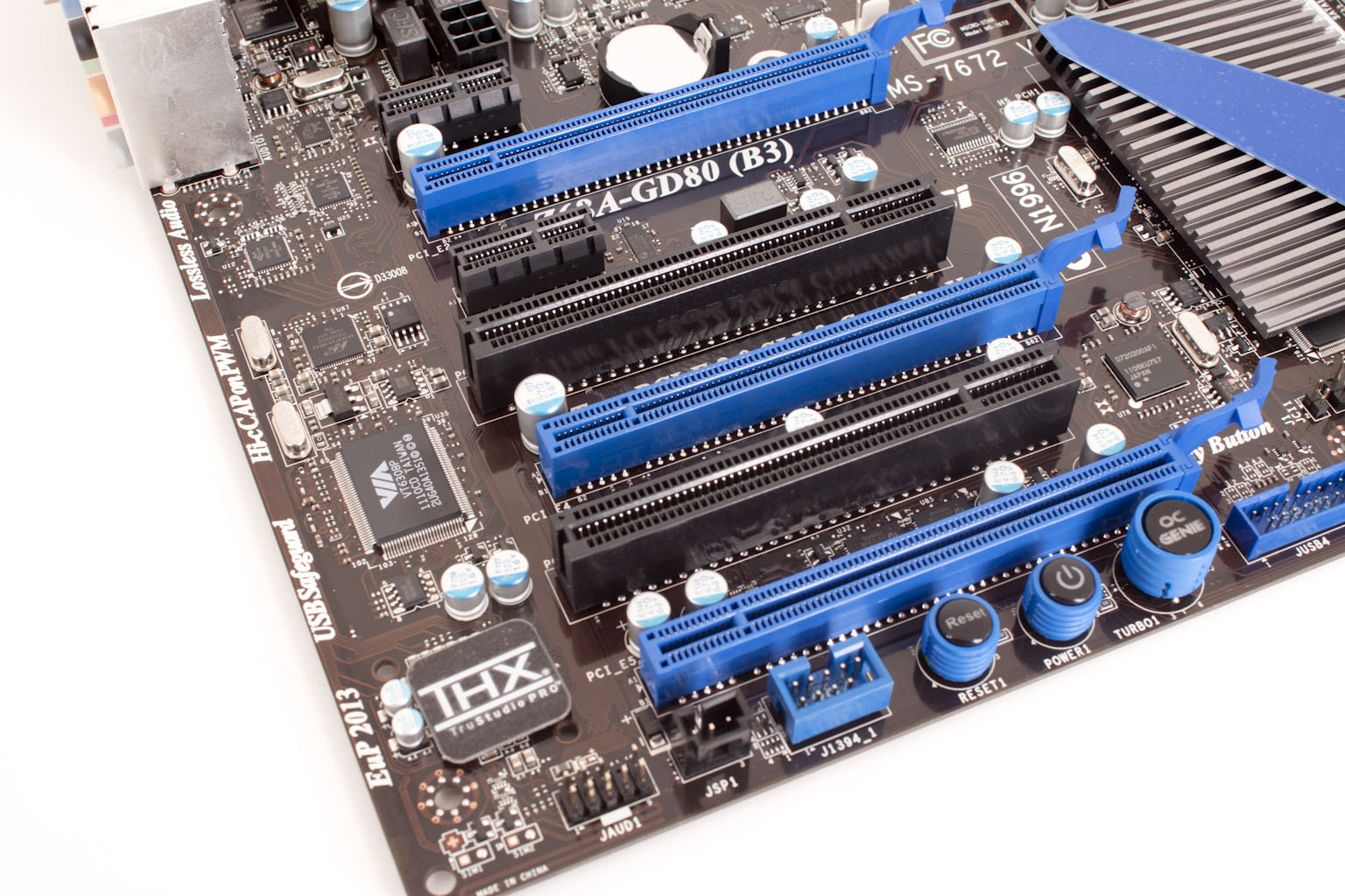
The THX audio sticker down here is covering a Realtek ALC892. This is a fairly good codec and adding the THX software on top only adds to its performance. Along the bottom edge of the board we get a good view of the board mounted controls. These are fairly typical but, still are nice to have there. The OC Genie button is something that we will talk about a little later and test in the second half of our review.

Flipping the Z68A-GD80 around we find a rather large heatsink over what we normally call the Southbridge but is really the MCP (Media Control Processor). We also get a look at the SATA ports; there are two SATA II ports, two SATA 3.0 ports that are run from the Intel host controller on the B3 stepping Cougar Point chipset. As an added bonus MSI has thrown in a Marvell controller to run an extra SATA 3.0 port and also an external SATA port on the back. It is this chip that you lose if you have an x4 or above PCI device in that last slot on the board.
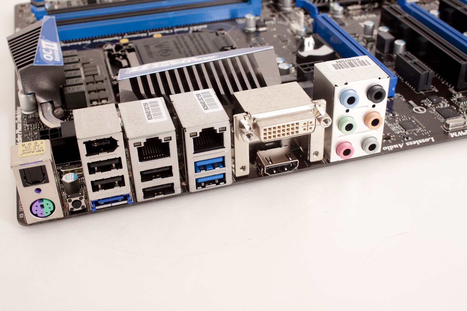
Now let’s take a look at the I/O ports we find an unusual choice. MSI has put the TOSLINK optical audio out on top of the dual purpose PS/2 port. Next to that there is a small flat press button that allows you to clear the CMOS without needing to open the case. In the next “stack” on the board we see that SATA 3.0 eSATA port we told you about. It is underneath a couple of more mundane ports. In addition you have two USB 3.0 ports, a DVI-I port, HDMI port, and the typical analog audio ports.
In all it the MSI Z68-GD80B3 is a well thought out board, with the notable exception of the lack of a bridge chip (PLX or another type) to prevent the loss of resources that happens when you have the last PCIe x16 slot filled. Now it is up to us to see if these choices can turn into performance.
